 En
En
 فا
فا
Battery Charger
|
BATTERY CHARGER Sepahan method electronic is able to design & manufacture industrial rectifiers and battery chargers in a variety of conventional, doublex & parallel. All stages are done by our experts, so various features can be added according to customer request.
|
General Batteries Charger |
|
Design Criteria
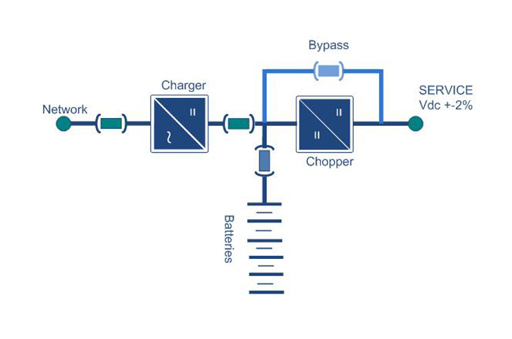
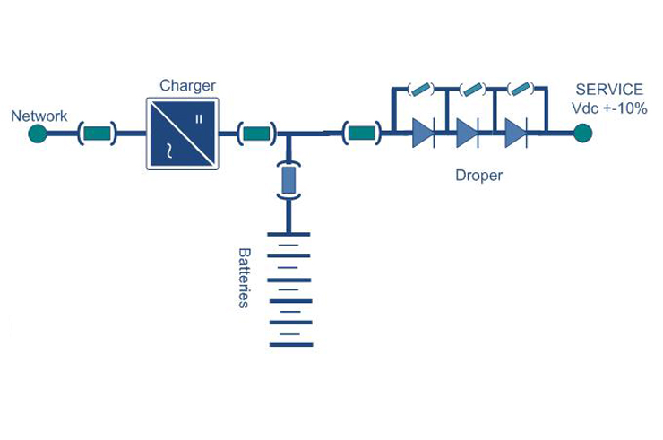
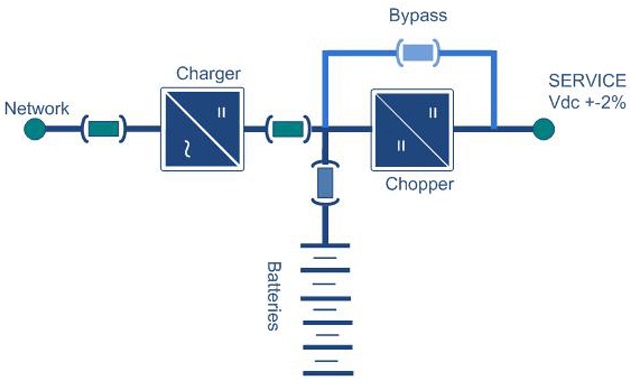
First solution First solution For having non-stop DC power supply : In the first solution we provide charger system and service system by the same rectifier cells.In case of higher currents, each dc power unit consist of two rectifier cells in 12-pulse configuration.The dc unit converts incoming AC power to DC which supply power to the connected loads and charges the battery at the same time in case of using chopper or dropper between rectifier and load( dropper for normal load and chopper for delicated load), the battery stores energy and is “floated” on the DC bus, ready to supply DC power to the load, as the input Ac supply voltage is is interrupted. During normal operation all rectifiers are operate in parallel to this cell will disconnect electrically from AC, the others shall carry the loads and failed cell will alarmed.The battery units shall be split for individual of line boost charging and shall automatically return to service in the event of an emergency. |
|
|
|
|
|
|
 |
 |
 |
 |
 |
|
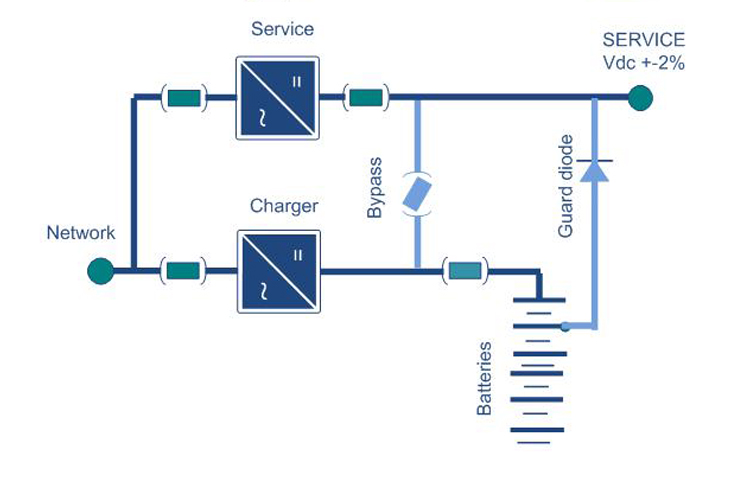
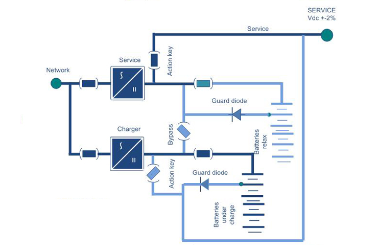
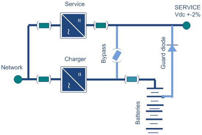
Second solution Second solution For having non-stop DC power supply :In second solution it will provide charging system separated from service system. In this case each Batteries charger consists of one rectifier cells for service loads & one rectifier cell for charging. That is connected in two separate DC bus. The rectifiers cells convert incoming AC power to DC power as specified before. The charger cells supply charging DC bus and could charge the batteries in boost charging mode while the other bus still working on desired voltage. The DC service bus also connected to batteries by power diodes and in case of fail of network the batteries (med point) will feed the service bus. The DC contactor is foreseen for connecting two DC bus in the time of failing network or in floating charge period The using in these way there is the possibility to mention DC service into desired voltage up to+ 1% In the case of failing charger cell there is the possibility to charge the batteries in floating mode through rectifier cells. |
|
|
|
 |
 |
 |
 |
|
Basic Construction
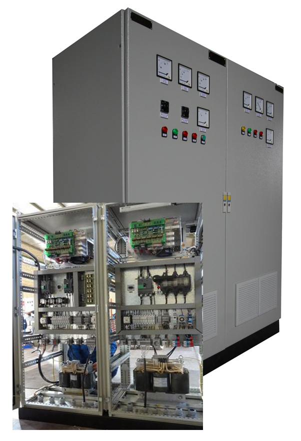
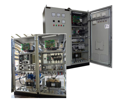
Rectifier cell The rectifier cells are static and full automatic type and dimensioned for 25 up to 500 Amp on desired voltage. The rectifier cells are Compact and easy removable type. In the event of any rectifier cell in fail the others in parallel should be operated independently Each rectifier cell is completely assembled and wired in draw able suitable case that is inserted in to charger unit. The rectifier cell will be connected to input and output by plug in material mounted in rear of cell. Any rectifier cell is equipped with the following; Input circuit breaker Input Contactor Input CTS Rectifier Bridge Filters Measuring device & inductor Out put fuse Capacitors charging devise Firing equipments & protection device Control system for any rectifier cell should be given by main control system (see drawing No.) The main cabinet shall be cleaned primed and painted with common practice produce.
Third solution For having more reliable non stop DC power supply (batteries charger) for rail application and sofisticated load.
|
|
Design Samples
|
|
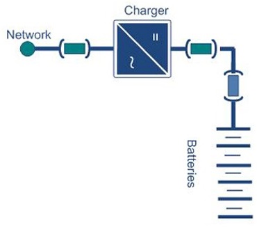
MNBC ( NORMAL BATTERIES CHARGER ) : |
|
Electrical characteristics Rectifier cell
AC input |
|
|||
|
Nominal voltage : Voltage range : Frequency : |
380 , 230 volt 3 phase 15% 50Hz, 60Hz ±5% |
 |
||
| DC output | ||||
|
Nominal voltage : Acceptable voltage range : Ripple : Efficiency : Batteries type : Batteries capacity : Charging mode : |
48 - 72- 96- 120- 240- 360 VDC with charging variation Max 3% in full load (1% in request) 95% Pb, Nicad 50- 150- 250- 500- 3000AH Constant current constant voltage as per standar |
|||
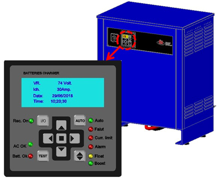 |
Indicators
Output DC current A Output DC voltage indicator Pilot lamp for charging capacitors (more in request)
|
Protection & signaling
Protection Phase fault Over current Over Temperature Short circuit |
||
|
Alarms and Status Indicators The alarm systems are displayed at the power cabinet by means of Mimic illuminated path whitch illuminate the switch situation and the illuminated enunciators will foreseen for following fault: AC input fail Rectifier cell Battery running down Battery low Short circuit
And also over any Rectifier is mounted the electronic cards and by subprint carda over it could find led indicator for normal operation . |
|
Earthing system All parts of cabinet should be connected in to good earth by means of wire into earth bus bar and all draw able part should be connected into earth by earthling blade.
|
|
MSBC (STABLIZED OUT BATTERIES CHARGER) :
Industrial, heavy duty Battery Charger module with full galvanic insulation. Is designed to supply DC loads with stabilized continuous supply meanwhile the system is charging the batteries for Industries such as Steel Oil & Gas, Petrochemical, Power & Utilities applications. |
|
||
|
Electrical characteristics Rectifier cell
AC Input: Nominal voltage : Voltage range : Frequency :
DC Output: Nominal voltage : Acceptable voltage range : Ripple : Voltage regulation : Efficiency : Batteries type : Batteries Capacity: Output capacity : |
380, 230 volt 3 phase 15% 50Hz , 60Hz ±5%
48 - 72- 96- 120- 240- 360- 480 VDC with charging variation Max 3% in full load 1% 95% Pb,Nicad 50-150-250-500-3000AH 50-150-250 Amp. |
||
| Alarms and status indicators
The alarm systems are displayed at the power cabinet by means of Mimic illuminated path whitch illuminate the switch situation and the illuminated enunciators will foreseen for following fault: AC input fail Rectifiers AC Main voltage Rectifier cell 1 fail Battery running down Battery low
And also over any Rectifier should be mounted the electronic cards and by subprint over it should find led indicator for normal operation . |
Protection & signaling Protection Phase fault Over current Internal Fault Over Temperature Min.& Max. network
Indicators Output DC current A Output DC voltage indicator Pilot lamp for charging capacitors |
 |
|
|
MRBC (REDUNDANT BATTERY CHARGER) :
Industrial, heavy duty Battery Charger module with full galvanic insulation. Is designed to supply DC loads with stabilized continuous supply meanwhile the system is charging the batteries for Industries such as Steel Oil & Gas, Petrochemical, Power & Utilities applications.
|
|
|
Protection & signaling Protection
Phase fault Over current Internal Fault Over Temperature Min.& Max. network
|
Indicators
Output DC current A Output DC voltage indicator Pilot lamp for charging capacitors
|
 |
|
Alarms and status indicators
The alarm systems are displayed at the power cabinet by means of Mimic illuminated path whitch illuminate the switch situation and the illuminated enunciators will foreseen for following fault: AC input fail Rectifiers AC Main voltage Rectifier cell 1 fail Rectifier cell 2 fail Battery running down Battery low
|
And also over any Rectifier should be mounted the electronic cards and by subprint over it should find led indicator for normal operation .
|
|
MFBC (FULL REDUNDANT BATTERY CHARGER) :
Industrial, heavy duty Battery Charger module with full galvanic insulation. Is designed to supply DC loads with stabilized continuous supply meanwhile the system is charging the batteries for Industries such as Steel Oil & Gas, Petrochemical, Power & Utilities applications.
|
|
|
Protection & signaling Protection
Phase fault Over current Internal Fault Over Temperature Min.& Max. network
|
Indicators
Output DC current A Output DC voltage indicator Pilot lamp for charging capacitors
|
 |
|
Alarms and status indicators
The alarm systems are displayed at the power cabinet by means of Mimic illuminated path whitch illuminate the switch situation and the illuminated enunciators will foreseen for following fault: AC input fail Rectifiers AC Main voltage Rectifier cell 1 fail Rectifier cell 2 fail Battery running down Battery low
|
And also over any Rectifier should be mounted the electronic cards and by subprint over it should find led indicator for normal operation .
|